

MICRO MILL & Microdynamics HMI: Tool Setup, Part Setup (G54), and G‑code in One Workflow
- Apr 20
- 6 min read
Why we built MICRO MILL into our HMI
When we talk to machinists, the same frustrations come up again and again: setup steps feel fragmented, offset work is error‑prone, and it’s too easy to lose time moving between tools, screens and devices.
Our answer is the MICRO DYNAMICS HMI, a Windows‑embedded HMI CNC environment designed to be flexible for operation and automation, and to let operators load, run, or edit programmes from internal HMI memory, a PC hard drive, or an external USB device.
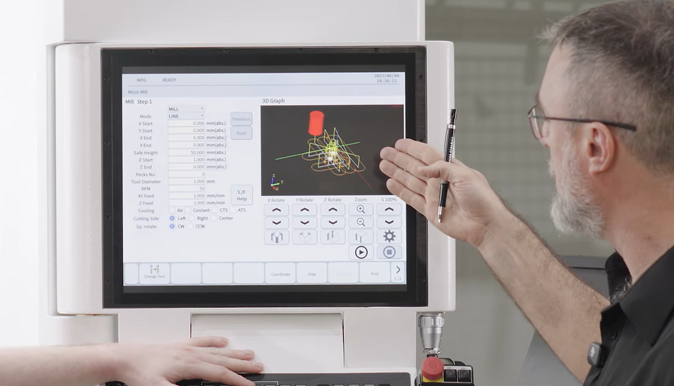
Inside that HMI, we built MICRO MILL: an interface that allows operators to perform milling and drilling operations while creating G‑code, then posting it to MDI or main memory.
In other words, rather than treating programming, measurement, and execution as separate “departments,” we try to keep the operator’s workflow coherent- especially for day‑to‑day parts, setup work, and quick jobs.
The setup workflow we follow on MEGA/TERA
Across our MEGA/TERA series, the operator goal is consistent: get tools and work offsets right, then cut confidently. Our CNC machines are designed for broad applications, and we pair them with fast control and features like thermal compensation technology (DYPEC) and HMI software intended to make operation comfortable.
Before we get into button‑by‑button actions, here is the practical flow we use:
Confirm the tooling plan and magazine readiness
Measure tools (tool setup)
Measure the workpiece reference position (part setup / work offset)
Generate the program steps in MICRO MILL
Post to MDI or memory, verify, and run
Manage files and use recovery tools when needed
Safety and training note
No HMI can replace safe practice. We expect operators to use equipment properly and in line with manufacturer instructions, and to ensure the machine is maintained, fit for use, and protected by appropriate safety measures such as guarding and emergency stops.
For CNC routers and machining centres, the UK HSE also publishes practical safe‑working guidance designed for employers and operators.
Tool setup and measurement in our HMI
Tool setup is where small mistakes become big problems. That’s why we focus on two things: (1) making measurement steps explicit and repeatable, and (2) giving operators visibility into what the magazine is doing.
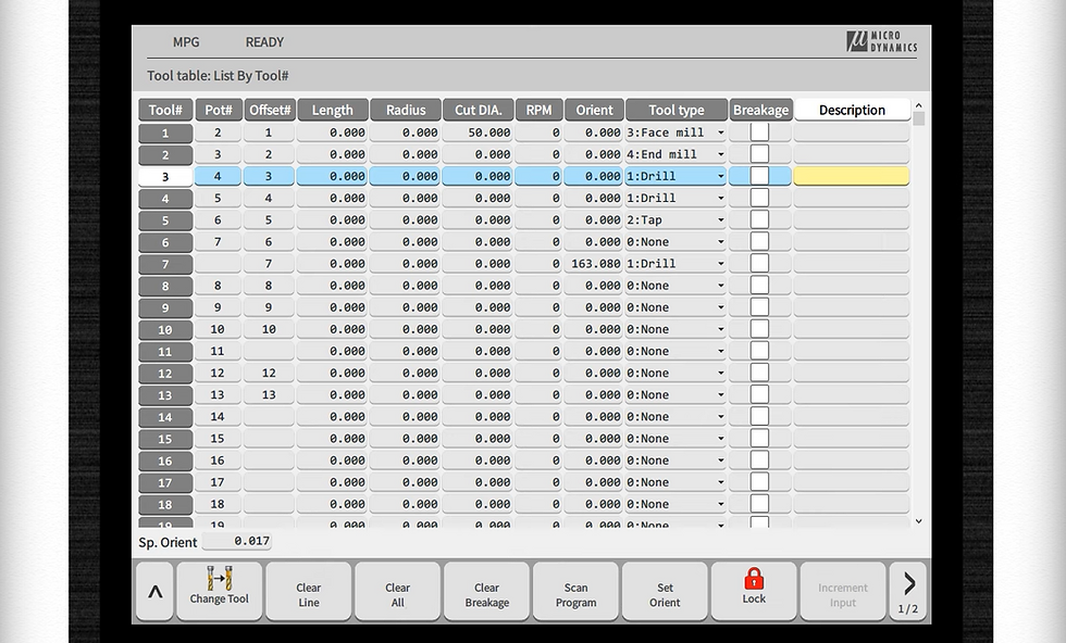
Tool list and magazine monitoring
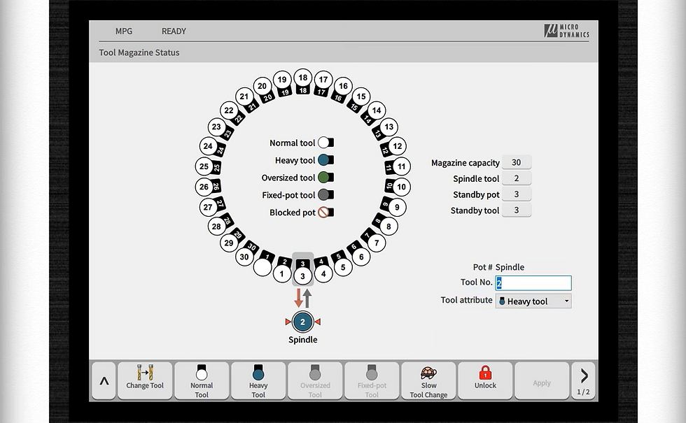
Within our HMI feature set, Magazine Monitor is designed to show tool magazine status and to support settings such as heavy tool, oversized tool, and fixed‑pot tool.
This matches what we demonstrate in the workflow: we show how operators can treat specific tools differently when they’re heavier or oversized, to reduce risk and keep motion predictable.
If your setup includes probing or tool measurement hardware, it’s also worth planning for that up front. Our machines have tool setup behaviour that can work with a Renishaw tool‑setting solution (where fitted), enabling users to select tools to measure and run measurement routines automatically.
Measuring tool length
Our Tool Setup "operation teaching" guide illustrates a simple operator pattern: choose the tool measure type, enter the work offset and tool offset context, enter gauge height, call the tool, move to the measurement point, and click Measure to capture coordinates.
We also demonstrate an “automatic tool measurement” approach where operators select the tools to measure and run a cycle to measure them, with an additional orientation step when required.
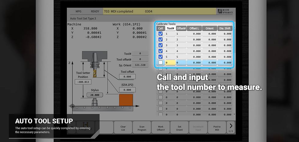

Regardless of whether you’re using manual/jog workflows or automated routines, our goal is the same: make tool measurement steps visible and structured so your offsets are ready before you cut.
Part setup and work offset measurement (G54…etc)
Once tools are measured, we move to workpiece setup. On our HMI page, we have Auto Part Setup with hard probing, where X, Y, and Z work offsets can be measured with a hard probe.
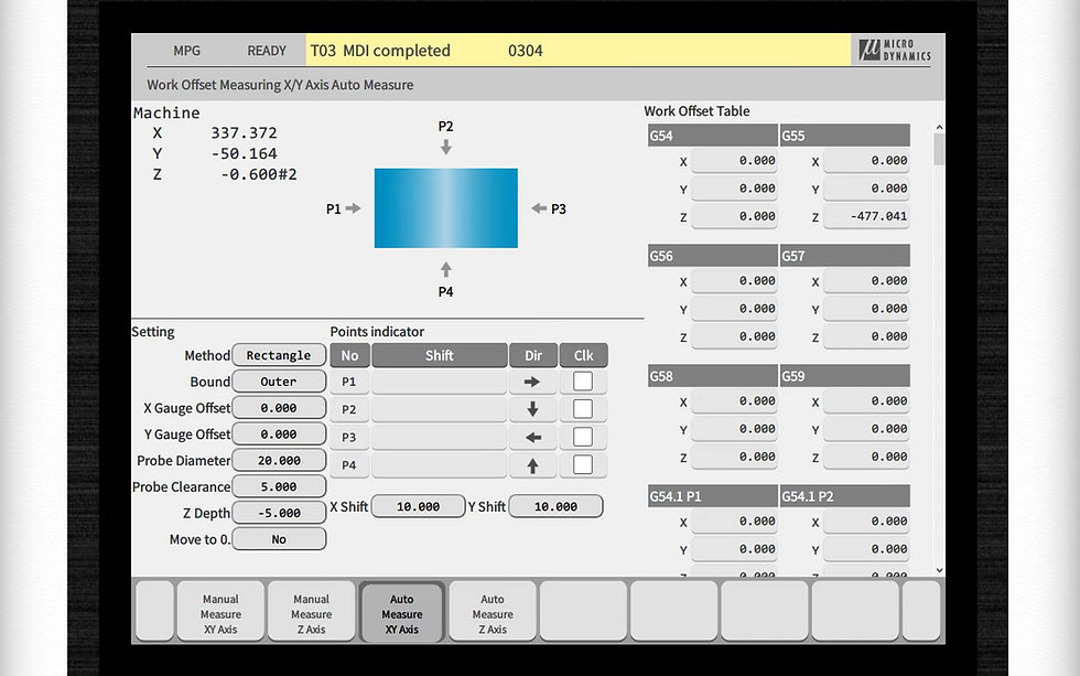

We also support part setup patterns for different workpiece shapes. The HMI page calls out “8 different patterns” for shapes including round and rectangular, and inner or outer circles, used when finding workpiece coordinates (G54…etc).
Choosing the right pattern
Our one‑page Part Setup operation teaching PDF shows the practical choice operators make first: select the method and bound (inner/outer) and define the setup gauge radius.
It then illustrates pattern options such as:
rectangle single: outer vs inner
rectangle multiple: outer vs inner
circle patterns (e.g., 1‑point, 3‑point, 6‑point): outer vs inner
We show a rectangle measurement workflow in which the operator positions the probe close to the part, sets clearance/shift values, selects the corner that will define the zero point, and runs the cycle to populate X and Y in the work offset table, then measures Z in a similar guided step.
Writing results to the work offset table
The Part Setup operation teaching sheet ends with the key action: write to work offset.
This is the moment where the measurement work becomes usable machining context, your G54 (or other) offset values are now ready for the program. The HMI positioning is very intentionally “operator‑first”: guided patterns, repeatable steps, and a clear end state.
Creating and running a simple part program with MICRO MILL
With tools and offsets ready, we move to programming. On our HMI page we define MICRO MILL as an interface that allows operators to perform milling and drilling operations while creating G‑code, then post to MDI or main memory.
Building steps: face, profile, pocket, drill, tap

We demonstrate creating a simple part by building sequential steps: face milling, contour/profile cutting, circular and square pocketing, drilling patterns, and tapping.
The key point is not the specific geometry; it’s that the operator is building a structured process where each step is explicit, reviewable, and posted in a controlled way.
This style of “step‑based” programming also supports operator confidence: you can see the steps accumulate, check the tool selection, and confirm the intended operations match the part plan before metal is cut. Viewing and editing the generated G‑code once created, reinforcing that MICRO MILL is not a black box, it’s a guided generator built for operational control.
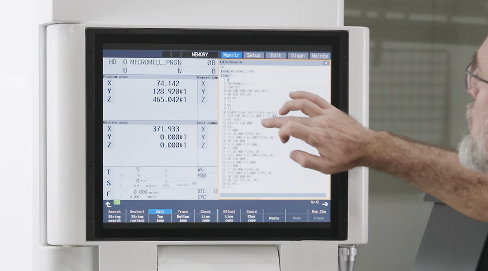
Posting to MDI or memory and checking before cutting
Our HMI page explicitly states MICRO MILL can post to MDI or main memory, which supports both quick cycles and stored programmes.
We also note that the MEGA/TERA series features a Mitsubishi CNC control, and our on‑site description highlights tool path graphics verification as a way to check G‑code before machining.
Files, recovery tools, and next actions
File management and USB workflow
On the HMI page, we include File Manager as part of the system, positioned as a user‑friendly approach to configuring parameters and streamlining setup work.
In the transcript, we show a practical operator outcome: copying a generated MICRO MILL programme to a USB device via the file manager.

Recovery functions and collision detection
We surface recovery tools directly in the HMI feature set: ATC Recovery allows the operator to recover the tool changer, and APC Recovery allows recovery of the pallet changer.
On our media page, we also describe ATC Recovery as enabling a one‑click choice to complete or cancel a tool change, reducing the need for manual intervention.
We also list Collision Detection as part of the HMI feature set.
In practice, this is about supporting calm operation: making it easier to avoid or respond to errors in a controlled way, especially during setup and first‑run conditions.
What we recommend you do next
If you want to see this workflow on your parts, we recommend three next actions:
Watch the video: Learn MICRO MILL in 5 Minutes | MICRO DYNAMICS HMI Made Easy
review our MICRO DYNAMICS HMI overview: https://www.microdynamicsfa.com/technology/hmi
watch our HMI content in Media → Videos: https://www.microdynamicsfa.com/media/videos
request a demo or talk to your regional team using Find Your Dealer or Contact Us
And if you are collecting reference materials for procurement or internal training, our downloads area provides current catalog and brochure materials. https://www.microdynamicsfa.com/download
MICRO DYNAMICS HMI overview → https://www.microdynamicsfa.com/technology/hmi
MICRO MILL: create G‑code on the HMI → https://www.microdynamicsfa.com/technology/hmi (MICRO MILL section)
Part setup (work offset patterns and “write to work offset”) → https://www.microdynamicsfa.com/_files/ugd/0b5e89_50a150340a644468bae3232380c93cac.pdf
Tool setup (measurement workflow) → https://www.microdynamicsfa.com/_files/ugd/0b5e89_dd34819c992a441da44c07a65ad80a9b.pdf
Machines overview (MEGA/TERA positioning) → https://www.microdynamicsfa.com/machines
MEGA 30V specifications and features → https://www.microdynamicsfa.com/machines/mega30v
TERA 50V specifications and features → https://www.microdynamicsfa.com/machines/tera50v
DYPEC thermal compensation technology → https://www.microdynamicsfa.com/technology/dypec
Built‑in spindle overview → https://www.microdynamicsfa.com/technology/spindle
Videos: MICRO DYNAMICS HMI Made Easy → https://www.microdynamicsfa.com/media/videos
Download catalog and brochures → https://www.microdynamicsfa.com/download
Find your dealer → https://www.microdynamicsfa.com/dealer
Contact us → https://www.microdynamicsfa.com/contact
External authoritative links with anchor text
Contextually relevant for this article (machining / CNC operation)
UK guidance on machinery safety (HSE) → https://www.hse.gov.uk/work-equipment-machinery/introduction.htm
Safe working practices for CNC routers and machining centres (HSE information sheet) → https://www.hse.gov.uk/pubns/wis22.htm
Machine tool probing and tool measurement systems (Renishaw) → https://www.renishaw.com/en/probing-and-tool-measurement-systems-for-machine-tools--6073
Probing cycles software (Inspection Plus) (Renishaw) → https://www.renishaw.com/en/inspection-plus-macro-software-for-cnc-machine-tools--6094
M800V/M80V programming manual (Mitsubishi Electric CNC) → https://www.mitsubishielectric.com/dl/fa/document/manual/cnc/ib1501621/ib1501621-1501622enge.pdf


Comments